FAQ
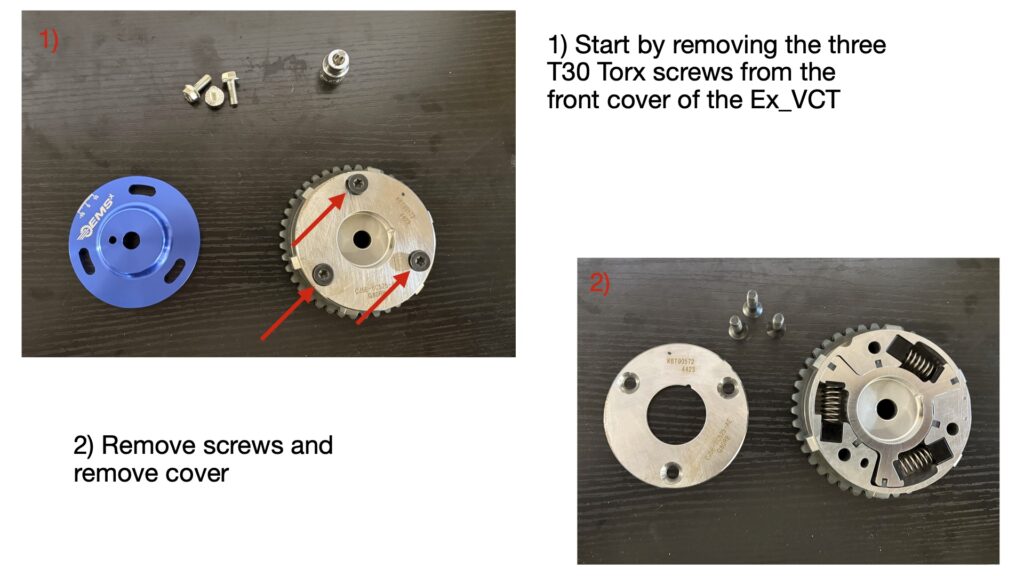
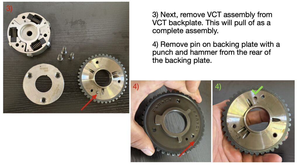
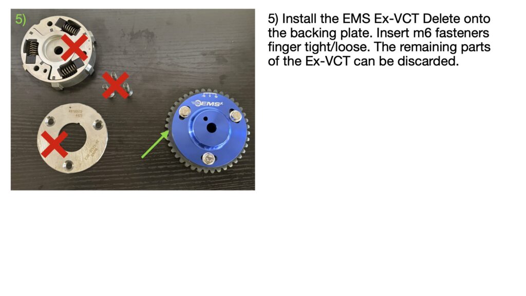
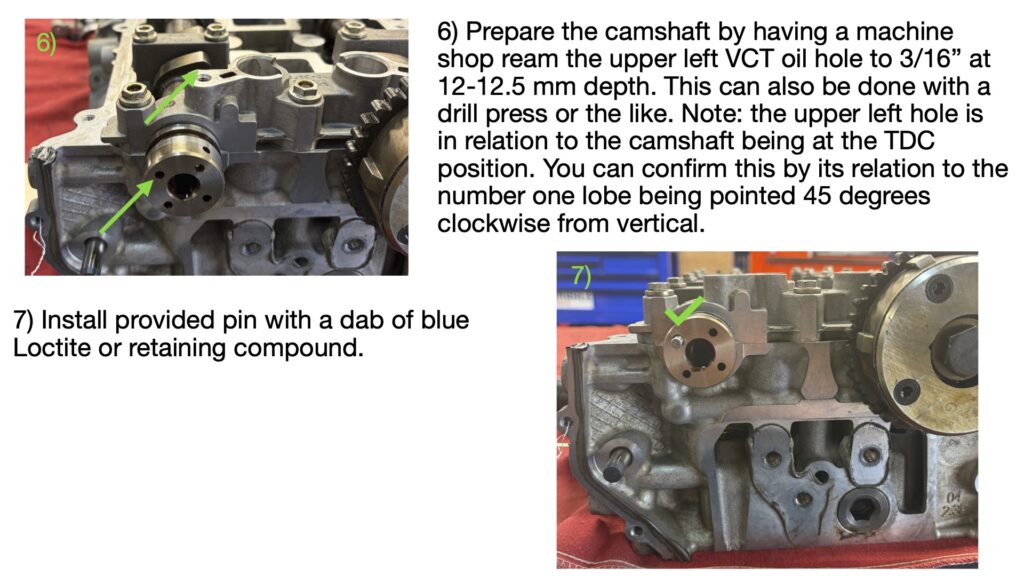
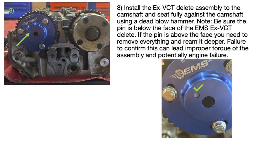
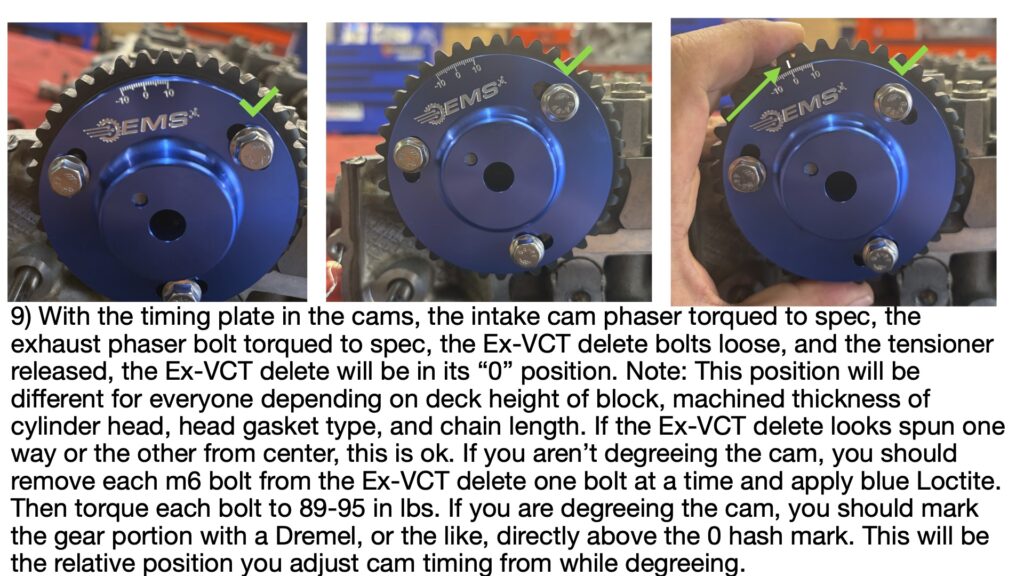
EMS Ex-VCT Delete — Installation Instructions For: 2.0L / 2.3L EcoBoost Engines
EMS 3.0L CA625+ TQ Specifications
1.) Make sure the threads in the block are clean and free from debris.
A. Blow head bolt holes out with compressed air, in some situations you may need to
use a flat bottoming tap to properly clean the holes.
2.) Lightly coat the bottom of the stud with some of the provided ARP Ultra Lube or engine oil.
3.) Install the stud into the block hand tight.
A. Be sure to clean any excess lube or oil off of the deck surface once all studs are
installed.
4.) Install a new cylinder head gasket.
5.) Carefully slide the cylinder head on to the engine block.
A. Be careful to no hit the bottom of the head on the studs during installation.
6.) Install the washers with the knurled side down.
7.) Apply ARP Ultra Lube to the threads of the stud, the top of the washer (part that contacts
the nut), and the bottom of the nut.
8.) Following the torque sequence below, torque the nuts to 35 ft-lbs and loosen them 3 times
in a row.
9.) Finally, following the torque sequence below, torque the studs 35 ft-lbs, 55 ft-lbs, and then
100 ft-lbs.
For best results, we recommend letting the engine sit overnight and rechecking torque,
when possible.
EMS Engine Break-In Instructions
(EMS Engine BREAK-IN Instructions)
Important Clarification
EMS test stand validation is not a complete operational break-in.
This process confirms workmanship and assembly integrity only.
Final ring seating, load conditioning, and operational break-in must still be completed by the installer/end user in accordance with the EMS Break-In Policy outlined below.
Failure to complete required break-in procedures may affect warranty eligibility.
Warranty begins the day engine is shipped or picked up by customer.
Shipping Inspection Requirement
All EMS engine shipments must be inspected at the time of delivery.
The recipient is responsible for carefully examining the crate and contents for any visible damage before signing for the shipment.
If damage is observed:
• Note the damage clearly on the delivery receipt before signing
• Photograph the crate and affected areas immediately
• Contact EMS within 24 hours
Signing for a shipment without noting visible damage confirms that the engine was received in acceptable condition.
EMS cannot be responsible for shipping damage that is not documented at the time of delivery.
We strongly recommend inspecting all freight deliveries thoroughly prior to acceptance.
1) EMS Pre-Shipment Craftsmanship Validation
(Sealed Engine Program Only)
Each EMS Sealed Engine is individually validated prior to shipment.
This in-house validation cycle is performed to confirm craftsmanship, mechanical integrity, and assembly quality before the engine leaves our facility.
During this controlled test stand process, the engine is:
• Brought to full operating temperature
• Operated through variable RPM ranges
• Subjected to controlled variable throttle load
• Monitored for proper oil pressure
• Inspected for oil and coolant leaks under load
• Verified for fluid level stability
• Checked for overall mechanical integrity
Conventional oil is used during this validation process.
Following the validation cycle, the engine oil and filter are replaced prior to shipment.
2. Initial Break-In Oil & Filter Requirements
(Mandatory for Warranty Compliance)
⚠️ THIS ENGINE REQUIRES 7 QUARTS OF OIL.
Upon receipt and installation of the engine, the following oil and filter requirements are mandatory for the first 500 miles of operation.
Oil Type – First 500 Miles
• Conventional (non-synthetic) engine oil is required.
• Break-in oil is acceptable.
• Synthetic oil is not permitted during the initial 500-mile break-in period.
• Oil viscosity must fall within the 5W-30 to 10W-40 range unless otherwise specified by EMS for your application.
Conventional oil is required to promote proper piston ring seating and controlled wear stabilization during initial operation.
Oil Filter Requirement
• Motorcraft FL400S oil filter is required.
• Use of non-OEM or aftermarket oil filters is not permitted during the break-in period.
EMS engines are built around OEM-based oil system specifications. Proper filtration and bypass characteristics are critical during initial break-in.
Failure to use the specified oil filter may affect warranty eligibility.
Oil Capacity: 7 quarts of full synthetic oil.
EMS built engines require 7 quarts of oil, which is 1 quart more than the typical OEM capacity of about 6 quarts.
Why do EMS engines use more oil?
Our engines are built with a balance shaft delete.
Balance shafts are used by manufacturers to reduce engine vibration by spinning weighted shafts inside the engine.
In many high-performance builds, these shafts are removed to:
- Reduce rotating mass
- Reduce internal drag
- Improve engine responsiveness
- Improve reliability in high horsepower applications
When the balance shaft assembly is removed, it frees up additional space in the oil pan and oil system, which allows the engine to safely run a slightly larger oil volume.
Because of this, EMS engines require 7 quarts of oil instead of the factory 6 quarts.
Oil change procedure
When changing oil:
- Drain the existing oil completely
- Replace the oil filter
- Fill with 7 quarts of full synthetic oil
- Start the engine and allow oil to circulate
- Shut the engine off and verify the level on the dipstick
Always confirm the oil level after the engine has run.
500-Mile Service
At 500 miles:
• Oil and filter must be replaced.
• Motorcraft FL400S filter must be used again.
• Oil should remain conventional for continued stabilization unless otherwise directed in Section 4 below.
Oil change documentation (date and mileage) should be retained for warranty purposes.
3. Initial Startup Data Log Requirement
(Mandatory for All EMS Engine Installations)
A startup data log is required for every EMS engine installation.
This requirement applies to all engines regardless of whether the vehicle is tuned by EMS or by a third-party calibrator.
Submission of startup data is mandatory for warranty validation.
When the Log Must Be Performed
The first startup log must be recorded:
• Immediately following initial engine start
• After confirming proper oil and coolant levels
• Before normal driving or load operation
The vehicle must not be operated beyond light throttle and controlled RPM conditions until the startup log has been completed.
Logging Parameters
Important:
Logging requirements differ depending on vehicle platform, model year, ECU strategy, and tuning software.
The parameters listed below are examples of commonly required channels and may vary by application.
Installers and tuners must contact EMS prior to startup to confirm the correct logging parameters for their specific engine, vehicle platform, and tuning software.
Failure to log the appropriate channels for your application may affect warranty eligibility.
Example Required Channels
• Air Fuel Ratio (AFR)
• Low Side Fuel Pressure
• High Side Fuel Pressure (if applicable)
• Ignition Timing
• Knock Retard / Knock Activity
• Coolant Temperature
• Engine RPM
• MAP / Boost Pressure
If equipped, oil pressure should also be logged.
Logs missing critical channels may be rejected.
Log Duration and Operating Conditions
The startup log must:
• Run a minimum of 5–10 minutes
• Include stable idle monitoring
• Include controlled RPM variation between idle and 2,500 RPM
• Include light throttle transitions
• Avoid wide open throttle
• Boost is OK, no full throttle.
• Remain at or below wastegate spring pressure
This procedure verifies proper fueling, base calibration stability, cooling system operation, and absence of abnormal detonation during initial operation.
Log Submission Requirements
• Startup log must be submitted to EMS within 24 hours of initial engine start.
• Submission must include customer name, order number, engine configuration, vehicle platform, and tuner information if applicable.
• Logs must be emailed to: [sales@emsinc-tn.com]
EMS reserves the right to request additional logs or documentation prior to approving continued operation.
Failure to submit required startup data may affect warranty eligibility.
4. Initial 0–500 Mile Break-In Procedure
(Mandatory)
The first 500 miles are critical for ring seating and bearing stabilization. The following limits must be followed.
RPM Limit
• Do not exceed 4,500 RPM during the first 500 miles.
• Avoid sustained high-RPM operation.
• Vary RPM within the permitted range.
Boost and Load Limit
• No wide open throttle.
• Boost must remain at or below wastegate spring pressure.
• Avoid sustained boost events.
Controlled, moderate load with varying throttle input is recommended.
Driving Restrictions
During the first 500 miles:
• Avoid extended steady highway cruising.
• Do not lug the engine under load.
• No hard launches.
• No racing or competitive driving.
• No dyno tuning.
500-Mile Service
At 500 miles:
• Replace oil and filter per Section 2.
• Inspect for leaks or abnormal conditions.
Full load and final tuning may proceed after completion of the 500-mile service.
5. Warranty Compliance
Compliance with Sections 2, 3, and 4 is required for warranty consideration.
The following are mandatory:
• Proper break-in oil and filter usage
• Submission of required startup log
• Adherence to RPM and boost limits
• Completion of 500-mile oil service
Warranty may be affected by:
• Missing startup logs
• Excessive RPM or boost during break-in
• Improper oil or filter usage
• Improper installation or mechanical negligence
• Detonation or lean operation during startup
Each claim is reviewed individually.
Even in situations where warranty coverage cannot be approved, EMS remains committed to supporting our customers. Our goal is to help
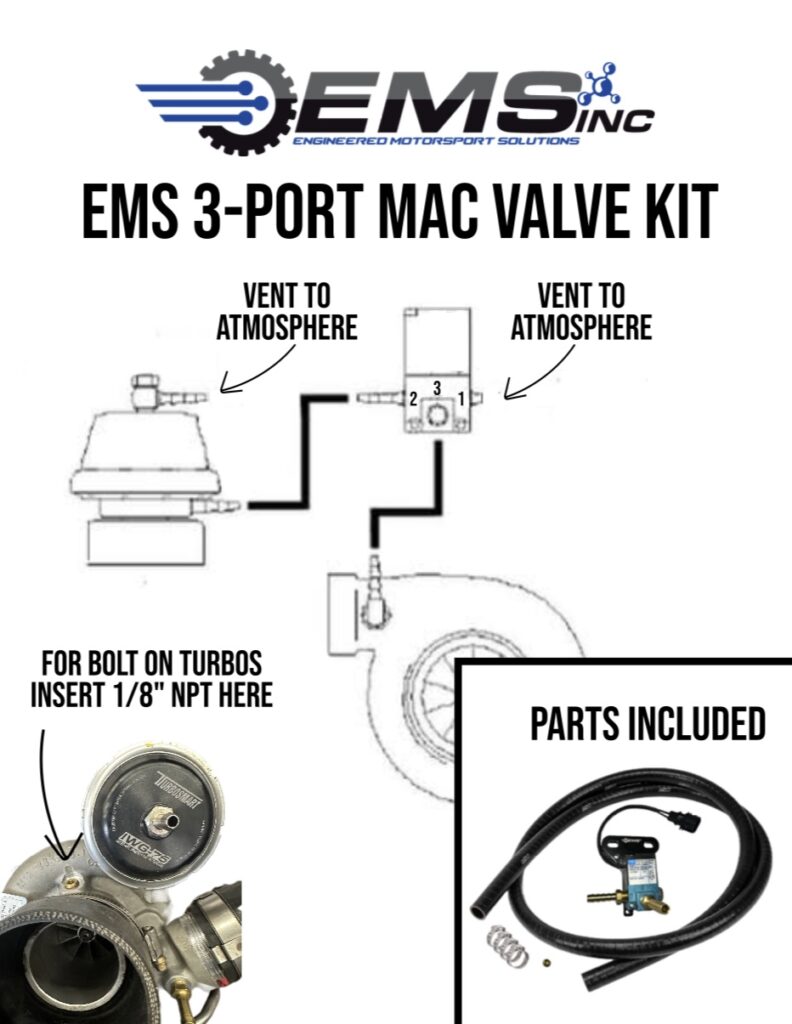
EMS – 3-PORT MAC VALVE KIT Installation Guide
XDI DI Injector Double Seals and Injector Removal
Selecting Parameters With Your Cobb AP
EMS 2.0/2.3L Spec Ca625+ TQ Specifications
1.) Make sure the threads in the block are clean and free from debris
A. Blow head bolt holes out with compressed air, in some situations you may need to
use a flat bottoming tap to properly clean the holes
2.) Lightly coat the bottom of the stud with some of the provided ARP Ultra Lube or engine oil
3.) Install the stud into the block hand tight
A. Be sure to clean any excess lube or oil off of the deck surface once all studs are
installed
4.) Install a new cylinder head gasket
5.) Carefully slide the cylinder head on to the engine block
A. Be careful to no hit the bottom of the head on the studs during installation
6.) Install the washers with the chamfer side down
7.) Apply ARP Ultra Lube to the threads of the stud, the top of the washer (part that contacts
the nut), and the bottom of the nut
8.) Following the torque sequence below, torque the nuts to 35 ft-lbs and loosen them 3 times
in a row
9.) Finally, following the torque sequence below, torque the studs 35 ft-lbs, 55 ft-lbs, and then
80 ft-lbs.

For best results, we recommend letting the engine sit overnight and rechecking torque,
when possible.
Long Block Assembly
How to install Aux Fuel Adapter and Rail
When adding more power, you’ll need more fuel.
Here’s our step-by-step instruction on >> How to install Aux Fuel Adapter and Rail?
EMS EcoBoost Mustang 1.16 60’ Suspension Setup
Rear Main Seal Install on 2.0 & 2.3 Liter EcoBoost Engines
EcoBoost Mustang grinding process for BNR 525 & 600 Turbos
Difference between TS, ST, and 2.3L blocks.
The TS block is identified by its semi-closed deck and the shared coolant jackets between cylinders. The 2.3 block is an open deck block and has a bolt-on water pump housing. This distinguishes the 2.3 blocks from the others and can lead to confusion when swapping to the ST or TS blocks.
READ ALL > What is the difference between the TS, ST, and 2.3L cylinder blocks?
33rd Annual Shootout 2026
2026 SHOOTOUT ECOBOOST CLASS FAQ
2026 Shootout EcoBoost Class Sponsored by EMS, Presented by RST Speedhaus

August 28–30, 2026
Summit Motorsports Park
Norwalk, Ohio
The EcoBoost Class returns to the 33rd Annual Shootout as part of the Mitsubishi vs. The World format.
This page contains important information for racers, spectators, vendors, and media.
GENERAL EVENT INFORMATION
What is The Shootout?
The Shootout is one of the longest-running import drag racing events in the United States, hosted annually at Summit Motorsports Park in Norwalk, Ohio. The event now features a “Mitsubishi vs. The World” format including DSM, EVO, GTR, Supra, EcoBoost, B58/S58, RB/JZ, and other modern performance platforms.
When is the event?
August 28–30, 2026.
Where is the event held?
Summit Motorsports Park
1300 State Route 18
Norwalk, OH 44857
ECOBOOST CLASS INFORMATION
Who is sponsoring the EcoBoost Class?
The 2026 EcoBoost Class is officially sponsored by EMS and presented alongside RST Speedhaus.
What vehicles are allowed in the EcoBoost Class?
The class is intended for Ford EcoBoost-powered platforms including:
- Mustang EcoBoost
- Focus ST
- Focus RS
- Fiesta ST
- Maverick
- Explorer ST
- F-150
- Ranger
- Bronco
- Fusion Sport
- Other EcoBoost-powered Ford platforms
Additional platform approvals may be determined by event staff.
Is this a street class or unlimited class?
The EcoBoost category is designed as a competitive drag racing class. Official class rules, tire requirements, safety regulations, and technical requirements will be released by event organizers and class sponsors.
Will there be payouts or awards?
Payouts, contingency programs, sponsor awards, and class-specific prizes will be announced closer to the event date.
RACER INFORMATION
How do I register?
Racers must register through the official Shootout registration system. Registration links and racer ticketing are available through TheFOAT and official event channels.
Are helmets and safety equipment required?
Yes. All racers must comply with applicable NHRA and event safety regulations.
Will tech inspection be required?
Yes. All race vehicles are subject to technical inspection before competition.
Can I daily drive my car to the event?
Yes. Many competitors drive their vehicles to and from the event, but all participants are responsible for ensuring their vehicles meet safety requirements.
SPECTATOR INFORMATION
Can spectators attend all three days?
Yes. Single-day and three-day spectator passes are available.
Is parking available?
Yes. General parking and VIP parking options are available through the event.
Will there be vendors and food?
Yes. The event typically includes vendors, sponsor booths, food vendors, car shows, and other attractions throughout the weekend.
MEDIA & CONTENT
Can media creators attend?
Yes. Media coverage is a major part of the event. Professional photographers, videographers, and automotive content creators are encouraged to participate.
Will EMS be documenting the event?
Yes. EMS plans to provide event coverage, racer features, behind-the-scenes content, and EcoBoost class media throughout the weekend.
IMPORTANT NOTES
Vehicle Modification Disclaimer
Participation in motorsports activities involves risk. All racers assume responsibility for vehicle safety, mechanical condition, and compliance with track regulations.
OFFICIAL EVENT LINKS
EMS Engines
MAP Billet EcoBoost Rear Main Seal
This installation guide is designed to walk you through the proper procedure for installing the MAP Billet Rear Main Seal on 2.3L EcoBoost engines. Following these steps ensures proper sealing, helps prevent oil leaks, and reduces the risk of rework during engine installation.
The MAP Billet Rear Main Seal is available to order directly through us at EMS. If you have any questions about fitment or installation, our team is here to help.
A full installation video is currently available on our Instagram, Facebook and YouTube.
MAP Billet EcoBoost Rear Main Seal INSTALLATION:
Tools You’ll Need
- Ford RTV — Part # TA-357
- Ford Prep Wipes
- 5mm Allen socket
- Torque wrench
- Blue Loctite
- Assembly lube or engine oil
Step 1
Clean block and seal surfaces
Remove all oil and debris using Ford Prep Wipes to ensure proper sealing.
Step 2
Let surfaces dry
Allow cleaner residue to fully evaporate before applying RTV.
Step 3
Lube the crankshaft end
Apply a thin layer of assembly lube or engine oil to prevent seal damage during install.
Step 4
Apply Ford RTV TA-357
Use a generous bead around the seal perimeter and oil pan junction to prevent leaks.
Step 5
Install seal at an angle
Set the seal at an angle to avoid wiping RTV off the oil pan surface.
Step 6
Apply blue Loctite to bottom two bolts only
These bolts go into the main girdle and require thread locker for proper retention.
Step 7
Hand-start all bolts
Thread all bolts by hand first to ensure proper alignment and avoid cross-threading.
Step 8
Torque to 89 in-lb
Tighten all bolts in a cross pattern to evenly seat the seal.
Step 9
Final inspection
Verify seal is flush, bolts are torqued, and RTV is properly applied.
Need Help Finalizing Your Setup?
If you have questions about configuration, compatibility, or dialing in your setup, contact us directly.
We’re available to help you spec the system correctly based on your build.
Call us (423) 500-4901 or
Email us at sales@emsinc-tn.com
WWW.EMSINC-TN.COM
How much oil does an EMS engine require?
Oil Capacity: 7 quarts of full synthetic oil.
EMS built engines require 7 quarts of oil, which is 1 quart more than the typical OEM capacity of about 6 quarts.
Why do EMS engines use more oil?
Our engines are built with a balance shaft delete.
Balance shafts are used by manufacturers to reduce engine vibration by spinning weighted shafts inside the engine.
In many high-performance builds, these shafts are removed to:
- Reduce rotating mass
- Reduce internal drag
- Improve engine responsiveness
- Improve reliability in high horsepower applications
When the balance shaft assembly is removed, it frees up additional space in the oil pan and oil system, which allows the engine to safely run a slightly larger oil volume.
Because of this, EMS engines require 7 quarts of oil instead of the factory 6 quarts.
Oil change procedure
When changing oil:
- Drain the existing oil completely
- Replace the oil filter
- Fill with 7 quarts of full synthetic oil
- Start the engine and allow oil to circulate
- Shut the engine off and verify the level on the dipstick
Always confirm the oil level after the engine has run.
Engine Shipping
Shipping an Engine to EMS?
Q: What parts do I send?
A: Only the engine long block — no accessories, pumps, belts, lines, or brackets.
Q: Do I need to drain the engine?
A: Yes, drain all oil and coolant before shipping.
Q: How should I secure the engine?
A: Place it exhaust-side down on a pallet and use four ratchet straps, tightening in two directions.
Q: How do I get the shipping label?
A: Measure and weigh your pallet and send that info to EMS. We generate the freight label and Bill of Lading and send them to you.
Q: What happens after I ship?
A: Deliver to your carrier with the label and BOL attached. We receive it at EMS and begin the rebuild.
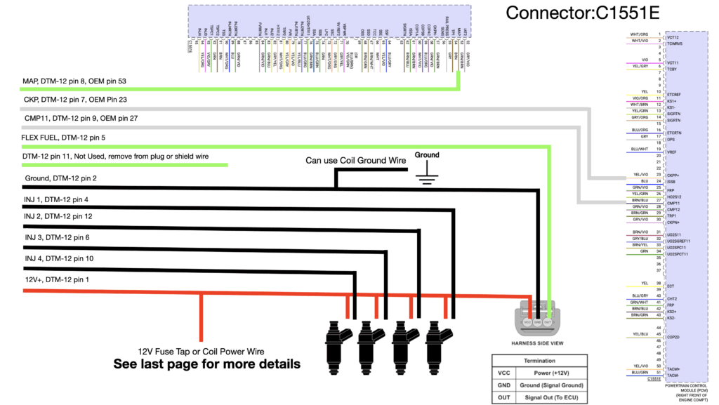
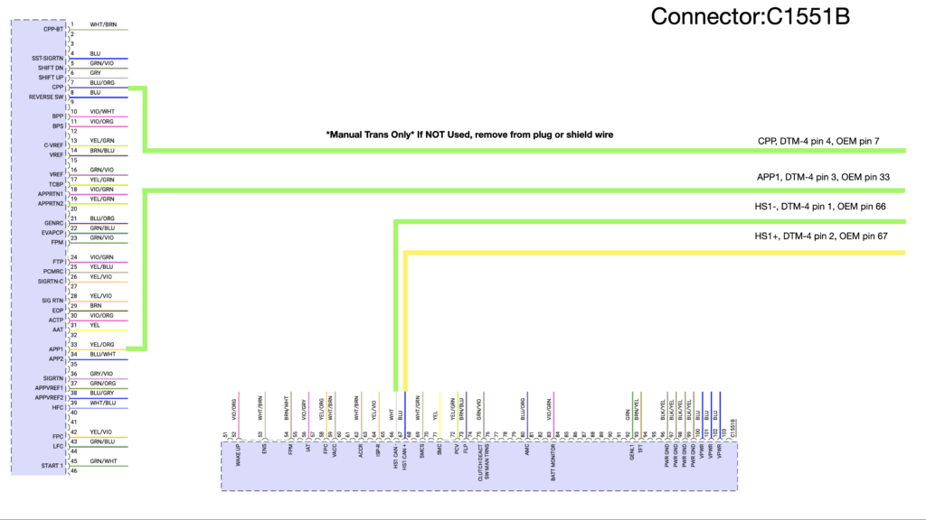
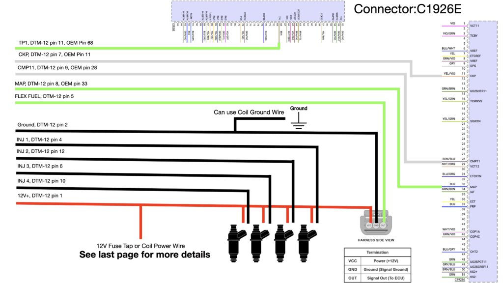
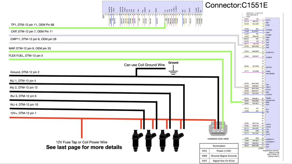
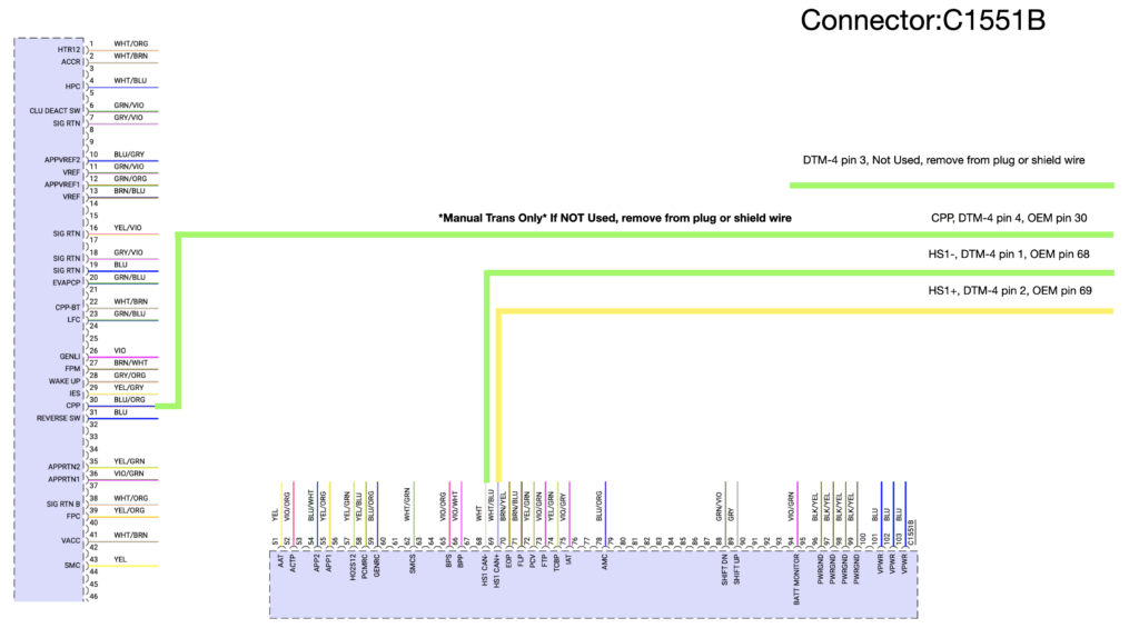
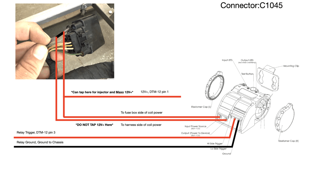
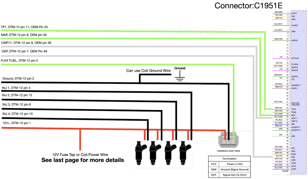
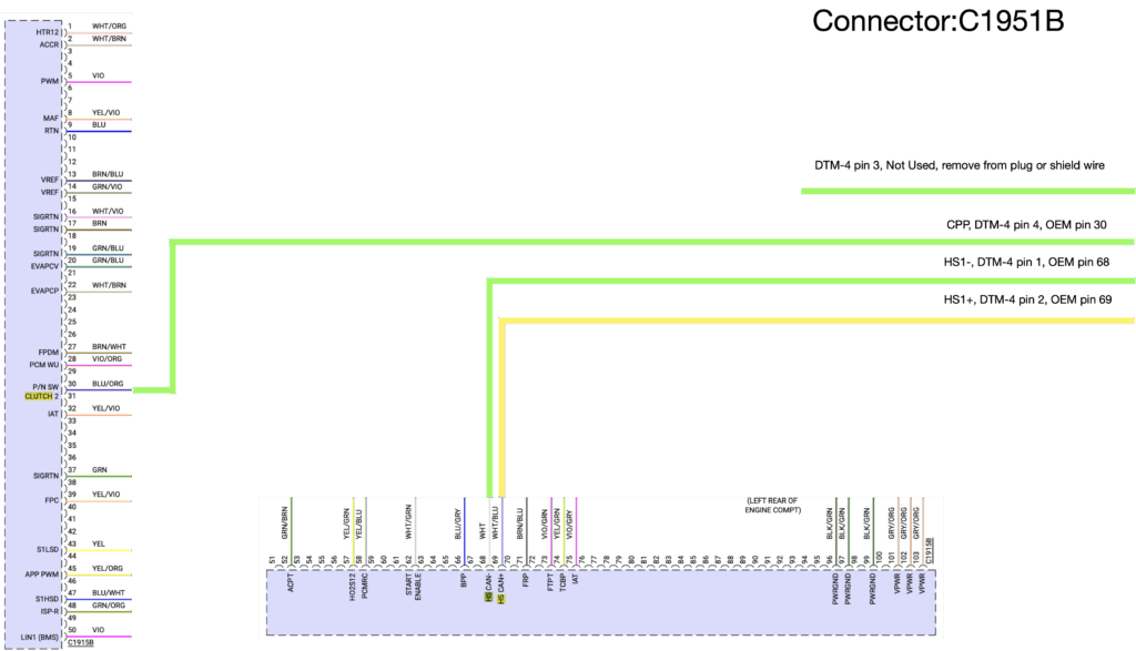
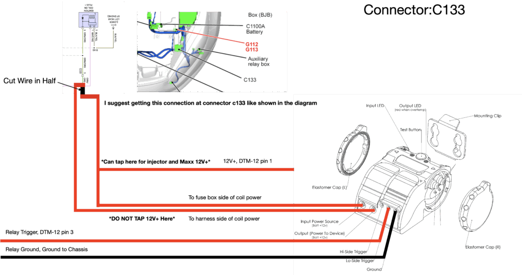
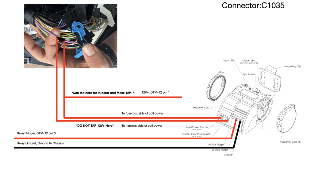
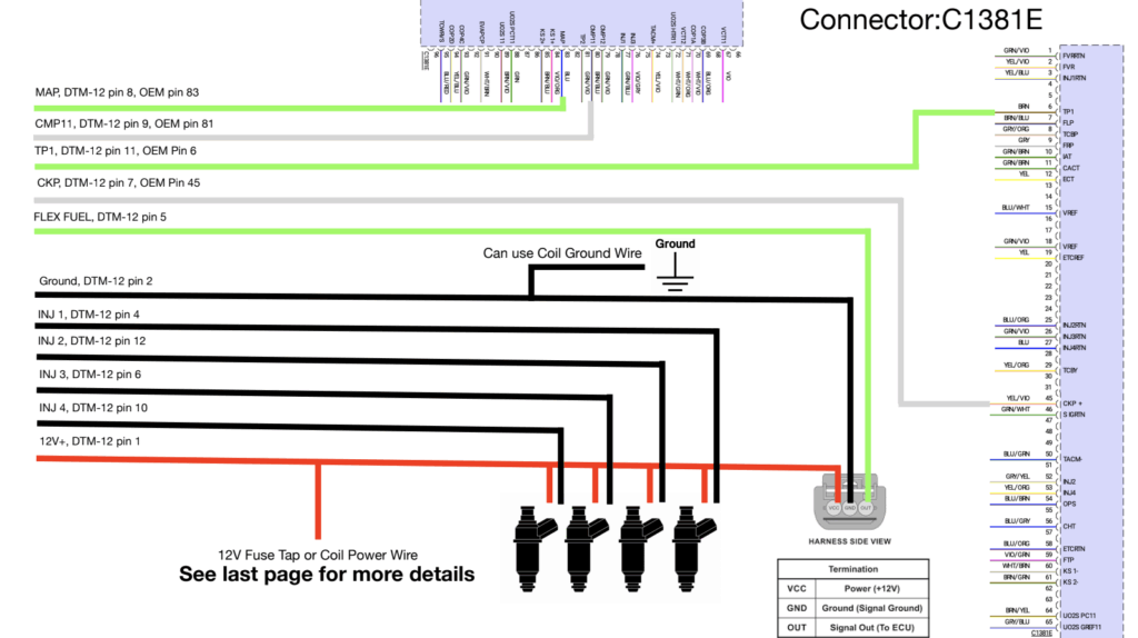
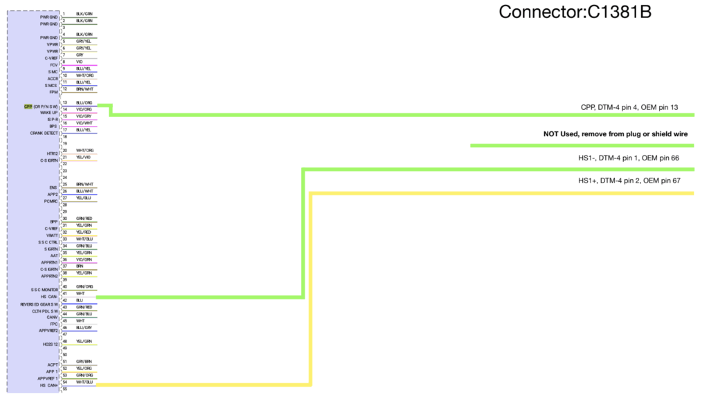
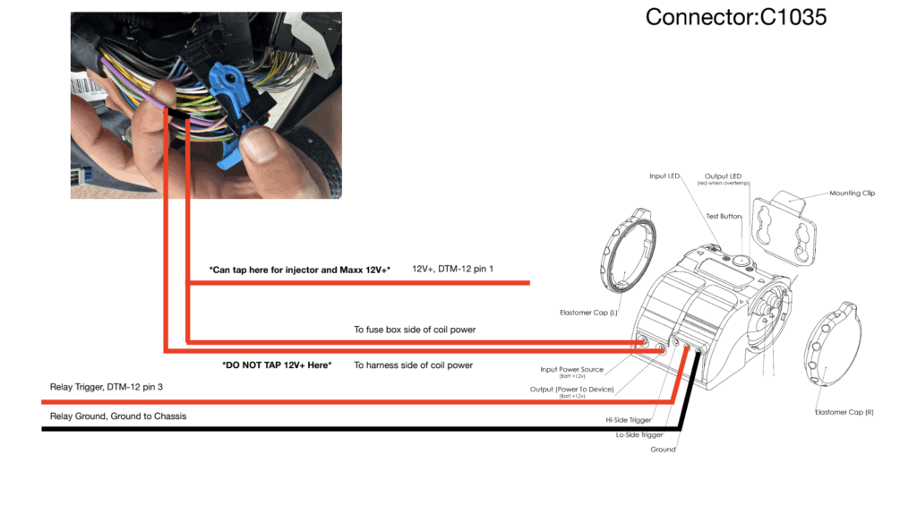
UAFS Wiring Guide
UAFS Wiring Guide 2016-2018 Focus RS
EMS Port Injection UAFS Wiring Guide 2016-2018 Focus RS – Jessie Ringley
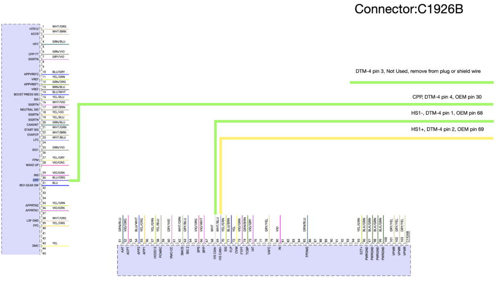
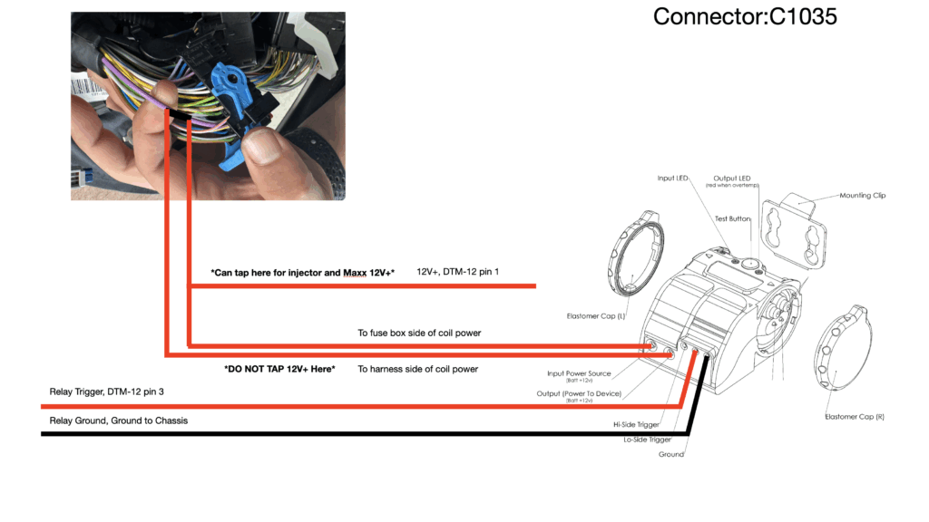
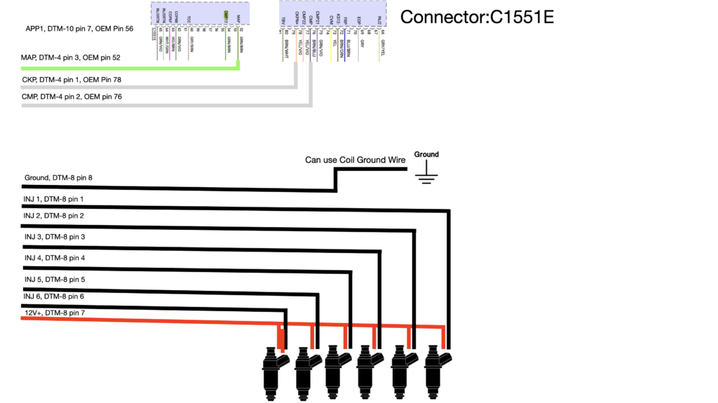
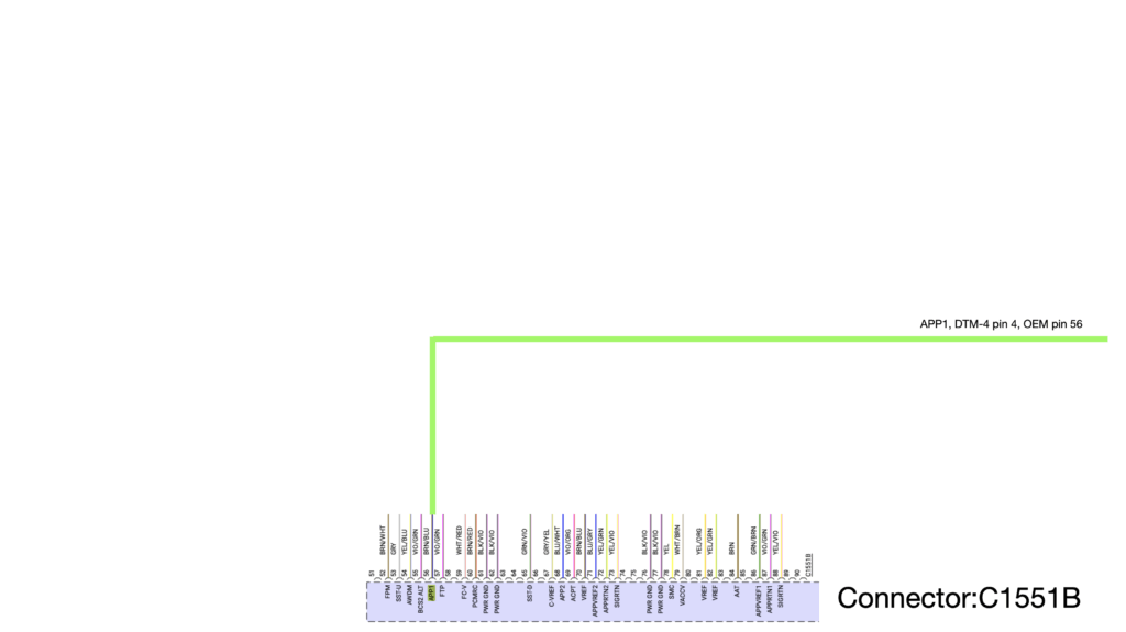
UAFS Wiring Guide 2015-2017 EcoBoost Mustang
EMS Port Injection UAFS Wiring Guide 2015-2017 EcoBoost Mustang – Jessie Ringley
UAFS Wiring Guide 2015 Fiesta ST
EMS Port Injection UAFS Wiring Guide 2015 Fiesta ST – Jessie Ringley
UAFS Wiring Guide 2020-2024 Explorer ST
EMS Port Injection UAFS Wiring Guide 2020-2024 Explorer ST – Jessie Ringley
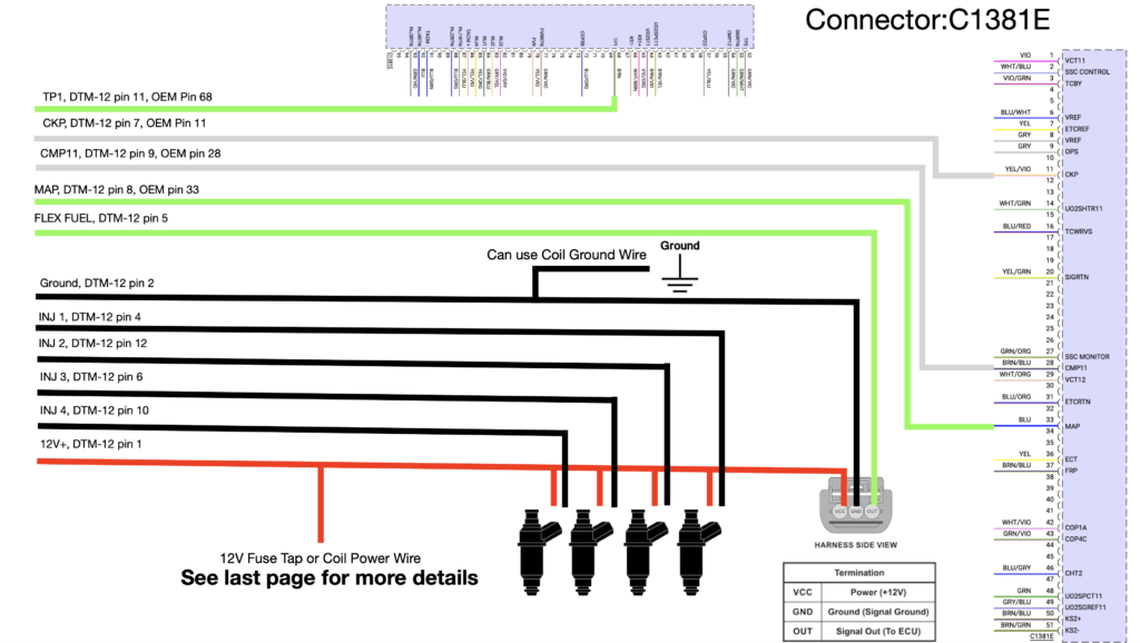
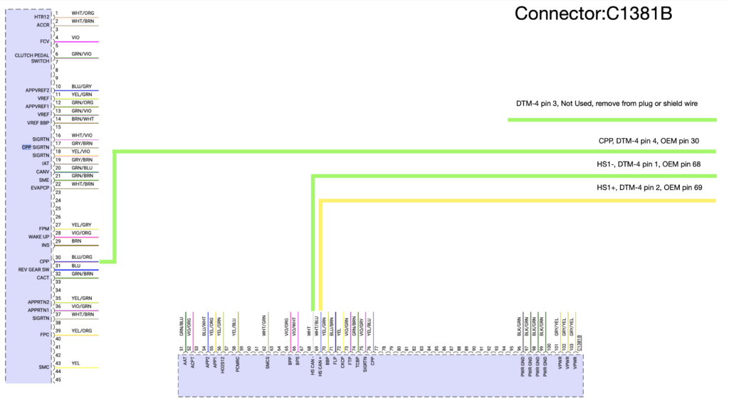
UAFS Wiring Guide 2015+ Focus ST
UAFS Wiring Guide 2015+ Focus ST – Jessie Ringley
UAFS Wiring Guide 2013-2014 Focus ST
UAFS Wiring Guide 2013-2014 Focus ST – Jessie Ringley
UAFS Wiring Guide 2018+ EcoBoost Mustang
UAFS Wiring Guide 2018+ EcoBoost Mustang – Jessie Ringley